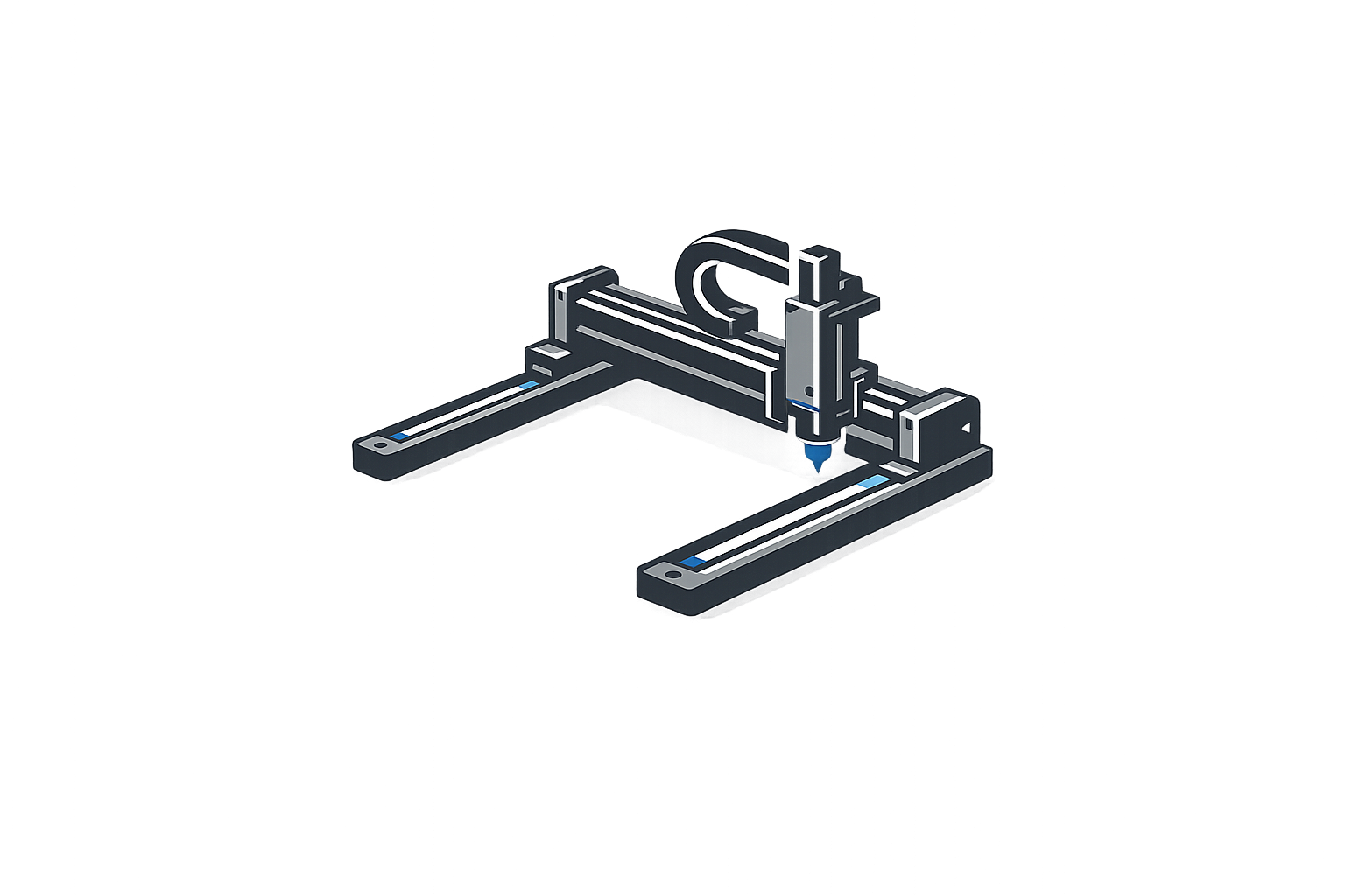
Precision Linear Motor Stages for Advanced Automation
Direct-drive linear positioning stages engineered for equipment manufacturers requiring zero-backlash motion, nanometer-level resolution, and rapid settling times.
Configure single-axis, XY, XYZ, and gantry structures based on your actual payload, travel, and controller compatibility requirements. We provide the mechanical foundation for high-speed inspection, assembly, and laser processing systems.
- Configurable travel: [Travel Range]
- Repeatability down to [Repeatability]
- Multi-axis synchronization support
- Confirmed drive/controller integration
Overcoming Critical Motion Control Challenges
Evaluating direct-drive systems requires looking beyond maximum speed. We help engineers resolve the practical integration constraints that affect real-world cycle times and measurement reliability.
High-Speed Settling Delays
The Constraint
When an inspection system completes rapid point-to-point moves, residual vibration delays image capture, reducing throughput even if nominal speed is high.
Engineering Response
We configure stages around your real payload and acceleration profile, matching encoder feedback to ensure the settling-time requirement is met, optimizing usable cycle time.
Thermal Drift & Accuracy
The Constraint
Continuous high-duty-cycle operation causes motor temperature rise, leading to structural expansion that alters positioning results over a production shift.
Engineering Response
By correctly sizing the continuous force against your duty cycle and utilizing appropriate thermal isolation or cooling options, we mitigate temperature-induced structural deformation.
Eccentric Load Deformation
The Constraint
Cantilevered payloads or high centers of gravity cause platform tilt, increasing wear on guides and destroying nanometer-level orthogonality.
Engineering Response
We analyze your payload's center of gravity to select guide rails with adequate moment-load capacity and optimize the stage width to maintain structural stiffness.
Multi-Axis Squareness Error
The Constraint
Stacking standard single-axis stages often introduces cumulative pitch, yaw, and squareness errors that compromise 2D or 3D volumetric accuracy.
Engineering Response
Our XY and XYZ systems are assembled and mapped as integrated units. We verify base flatness and orthogonality during assembly to guarantee final kinematic performance.
Controller Compatibility
The Constraint
Mismatches between the linear encoder protocol, servo drive commutation requirements, and the master motion controller halt commissioning.
Engineering Response
We review your existing drive and controller architecture before production, confirming signal types, resolution, and connector pinouts to ensure plug-and-play integration.
Cable Carrier Resistance
The Constraint
Improperly managed moving cables introduce variable resistance and vibration, degrading following error and causing premature cable fatigue.
Engineering Response
We design custom cable routing and specify high-flex life cables, minimizing parasitic drag and ensuring reliable operation over millions of high-acceleration cycles.
Linear Motor Stage Configurations
Single-Axis Linear Motor Stage
Provides fundamental point-to-point or constant-velocity motion. Ideal for integration as a base axis in custom machinery or for simple linear scanning. Selection requires evaluating travel, payload mass, and available base mounting interfaces to ensure structural rigidity.
- Travel: [Travel Range]
- Payload: Up to [Payload Capacity]
- High stiffness guide rails
XY Dual-Axis Linear Motor Stage
Engineered for two-dimensional planar positioning. Crucial considerations include maintaining strict orthogonality between axes, managing the stacked platform height, and routing cables without inducing parasitic drag. Common in semiconductor inspection and laser machining.
- Precision mapped orthogonality
- Integrated cable management
- Low-profile stacked design
XYZ Three-Axis Linear Motor Stage
Provides complete volumetric positioning. The design rigorously addresses Z-axis payload capacity, gravity counterbalance mechanisms, and the mitigation of stacked-stage cantilever errors. Demands high-level controller coordination for 3D path interpolation.
- Volumetric error compensation
- Z-axis pneumatic/magnetic counterbalance
- Center-of-gravity optimized
Gantry Linear Motor Stage
Utilizes a bridge or dual-drive arrangement for long-span, high-dynamics movement over a large work area. Requires advanced synchronized-axis control to prevent skewing and maintain gantry squareness under high acceleration. Ideal for large-format AOI and assembly.
- Dual-drive synchronization
- High structural stiffness bridge
- Large format travel capability
Vertical Linear Motor Stage
Specifically designed for vertical installation where gravity compensation is paramount. Selection hinges on accurate continuous-force calculation against the moving mass, and integrating reliable power-off brakes to satisfy equipment safety and holding requirements.
- Integrated power-off brake
- Gravity compensated design
- High-force motor selection
Configuration Comparison
| Product Type | Axes | Typical Application | Payload Consideration | Main Integration Risk | Customization |
|---|---|---|---|---|---|
| Single-Axis Stage | 1 | Linear scanning, feed mechanisms | Center of gravity relative to carriage | Base installation flatness | Travel, holes, cable routing |
| XY Dual-Axis Stage | 2 | Semiconductor inspection, alignment | Moment load on lower axis | Orthogonality error accumulation | Platform size, orthogonality spec |
| XYZ Three-Axis Stage | 3 | 3D metrology, precision dispensing | Z-axis mass affecting X/Y dynamics | Volumetric error, structural resonance | Z-axis stroke, counterbalance type |
| Gantry Stage | 2-3 | Large format AOI, laser cutting | Bridge stiffness under load | Dual-drive synchronization skew | Span width, dual encoder setup |
| Vertical Stage | 1 (Z) | Focusing, pick-and-place Z-axis | Constant gravity acting on motor | Power failure drop, thermal overload | Brake integration, force rating |
Engineering Note: Buyers should evaluate the complete motion requirement rather than isolating maximum travel or maximum speed. A stage's dynamic performance—including settling time and thermal stability—is heavily influenced by the interaction between the structural configuration, actual payload mass, and the motion profile. Read our Selection Guide.
How Direct-Drive Linear Motor Stages Work
Unlike traditional rotary systems, a linear motor stage generates force directly along the axis of motion. This eliminates mechanical transmission components like ball screws, couplings, and belts, removing backlash and mechanical elasticity from the drive train.
The system consists of a moving carriage (forcer) containing coils, gliding over a stationary magnet track. Precision guide structures—such as crossed-roller bearings or air bearings—ensure straightness and flatness. An integrated high-resolution linear encoder provides real-time position feedback to the servo drive and motion controller, enabling highly responsive closed-loop positioning.
The absence of screw transmission allows for exceptional acceleration and near-instantaneous settling times, but it also means the motor must directly bear external forces, making payload and thermal management critical during selection.
Learn More About Linear Motor TechnologyLinear Motor Stage vs. Ball-Screw Stage
Selecting the right transmission technology depends on your specific speed, duty cycle, and precision requirements. We offer objective guidance based on application physics.
| Feature | Direct-Drive Linear Motor | Traditional Ball-Screw |
|---|---|---|
| Transmission & Backlash | Non-contact magnetic force; Zero mechanical backlash. | Mechanical screw contact; Inherent backlash (even if preloaded). |
| Speed & Acceleration | Extremely high (limited mostly by guide rails and payload). | Limited by screw whip (critical speed) and pitch. |
| Settling Behavior | Rapid settling; highly dependent on servo tuning. | Slower settling due to mechanical elasticity and friction. |
| Holding Force | Requires continuous power or external brake. | Inherent mechanical friction aids holding position. |
| Maintenance | Low wear (only guides/cables require maintenance). | Requires regular screw lubrication; susceptible to wear. |
When to use Ball-Screw Stages
Ball-screw technology remains appropriate for applications with lower speed requirements, cost-sensitive machinery, moderate duty cycles, or when the system needs to maintain position against external forces without consuming continuous current (holding force).
When to use Linear Motor Stages
Direct-drive is superior for rapid scanning, short cycle times, repeated sub-micron positioning, high acceleration profiles, precision optical inspection, and continuous automation where mechanical wear would unacceptably degrade accuracy over time.
Standard Technical Specifications
| Travel Range | [Travel Range] (Customizable) |
|---|---|
| Positioning Accuracy | [Positioning Accuracy] |
| Bidirectional Repeatability | [Repeatability] |
| Maximum Speed | [Maximum Speed] |
| Maximum Acceleration | [Maximum Acceleration] |
| Continuous / Peak Force | [Continuous Force] / [Peak Force] |
| Maximum Payload | [Payload Capacity] |
| Encoder Resolution | [Encoder Resolution] (Optical/Magnetic options) |
| Straightness / Flatness | Depends on travel length, typically [Straightness] / [Flatness] |
| Environmental Options | Standard / Cleanroom [Cleanroom Class] / Vacuum [Vacuum Rating] |
Note: Actual performance depends heavily on configuration, payload mass, installation base flatness, control parameters, cable force, travel length, and environmental conditions.
Systematic Stage Selection Guide
Avoid common integration failures by evaluating these critical project conditions step-by-step.
Motion Profile
- Required travel length
- Target speed & acceleration
- Required settling time
- Duty cycle & operating time
Load Dynamics
- Payload mass & dimensions
- Center-of-gravity position
- Horizontal/Vertical installation
- Multi-axis moving mass
Precision & Environment
- Positioning accuracy
- Bidirectional repeatability
- Cleanroom/Vacuum needs
- Available installation space
Integration
- Mounting-hole pattern
- Cable & hose requirements
- Encoder requirement
- Existing drive/controller
Accuracy, Repeatability and Settling Time
An inspection machine may repeat the same point consistently (repeatability) while still carrying a systematic positioning error across the complete travel (accuracy). A buyer must evaluate absolute accuracy, especially when stage coordinates must match camera, laser, or measurement-system coordinates.
Furthermore, encoder resolution does not equal accuracy. Final kinematic performance is influenced by base flatness, assembly alignment, payload center of gravity, cable force, thermal conditions, and error compensation techniques. Settling time—the delay before the stage is stable enough for processing—dictates true machine throughput.
Read the Positioning Accuracy Guide →Payload, Force and Thermal Management
Selecting a stage based solely on "maximum payload" often leads to failure. The motor must generate sufficient force to accelerate the payload mass while overcoming friction and, in vertical axes, gravity.
It is crucial to distinguish between Peak Force (available for short acceleration bursts) and Continuous Force (the RMS force required for the complete duty cycle). Exceeding continuous force limits causes motor heating. Thermal expansion directly affects encoder readings and structural dimensions, leading to thermal drift during continuous operation.
Request a Force and Payload ReviewMulti-Axis Integration Risks
Combining axes into XY, XYZ, or gantry systems introduces compounding engineering challenges. The moving mass of the upper axes becomes the payload for the lower axes, requiring larger motors and stiffer structures at the base.
Orthogonality, squareness, and structural stiffness must be managed to prevent coordinate calibration errors and error accumulation. Practical consequences include increased machine footprint, reduced usable travel, complex cable routing, and more demanding commissioning and maintenance access.
Encoder, Drive & Controller Compatibility
We do not claim universal, automatic compatibility. Successful integration requires confirming hardware and software handshakes. We help buyers avoid integration bottlenecks by verifying:
- Encoder signal type (Sin/Cos, BiSS, TTL) and resolution
- Drive continuous/peak current & voltage requirements
- Commutation requirements and motion protocols (EtherCAT, etc.)
- I/O for limit sensors, home sensors, and E-stop integration
- Cable connector pinouts and servo tuning support
Custom Linear Motor Stage Engineering
When standard products do not match your envelope dimensions, mounting holes, or environmental requirements, our engineering team provides tailored structural designs.
-
1
Requirement Review
Customer submits requirements or cabinet drawing. We review travel, load, accuracy, interface compatibility, and available space.
-
2
Configuration & Drawing
A specific configuration or customized mounting-hole drawing is prepared. The customer confirms the drawing.
-
3
Sample & Inspection
A sample or first article is produced when required. Inspection data is reviewed and sample approval is secured.
-
4
Batch Production
Batch production proceeds after sample approval, maintaining strict batch-production stability. Documentation and shipment are prepared.
Industrial Applications
Semiconductor Inspection
Requires moving a camera through repeated scan positions with a short settling window. Travel, encoder feedback, and payload inertia are evaluated together.
View XY Stages →Laser Processing
Demands constant velocity and zero mechanical backlash to ensure smooth cut edges. Gantry structures with synchronized drives are typical.
View Gantry Stages →Automated Dispensing
Needs precise 3D path interpolation. Z-axis payload capacity and counterbalance are critical for maintaining X/Y dynamics.
View XYZ Stages →Medical-Device Equipment
Often requires cleanroom compatibility. Materials, cable management, and surface treatments must prevent particle generation.
View Cleanroom Options →Optical Alignment
Sub-micron positioning accuracy is required. Thermal drift management and high-resolution encoder feedback are paramount.
View Single-Axis →Machine Vision
High-speed point-to-point moves with minimal residual vibration to capture sharp images immediately upon stopping.
View XY Stages →Precision Metrology
Volumetric accuracy requires strict multi-axis squareness, mapped error compensation, and high structural stiffness.
View XYZ Stages →Microscopy
Smooth, slow-speed scanning (low velocity ripple) with low profile designs to fit under optical instruments.
View XY Stages →Quality Verification Process
We verify stage performance using calibrated measurement equipment. Documented inspection data reduces your integration risk.
-
Positioning & Repeatability Test
Measured via laser interferometer under no-load conditions. [Placeholder for verification]
-
Straightness & Flatness Test
Verified using dial indicators and precision granite surface plates. [Placeholder for verification]
-
Multi-Axis Squareness
Assembly alignment checked via CMM or laser tracking. [Placeholder for verification]
Engineering Documentation
Available documentation should be confirmed for the selected configuration. Standard deliverables typically include:
Project Workflow
RFQ & Review
You submit payload, travel, and controller data. We review and recommend a configuration.
Drawing Confirmation
We supply dimensional and mounting-hole drawings for your approval before quotation.
Sample & Approval
First article produced if required. Inspection report provided for sample approval.
Batch & Support
Consistent batch production, shipment with documents, and commissioning support.
Manufacturing Capability & Trust
We back our engineering claims with visible factory evidence, verified certifications, and a history of offline technical consultations.
Company Certificates
- [ISO 9001:2015 Quality Management]
- [CE Certification for Motion Stages]
- [RoHS Compliance]
Global Trade Shows
We actively participate in industry exhibitions to discuss motion-stage demonstrations and technical consultations with buyers directly. We maintain 8 sets of offline trade-show materials.
Assembly area & Inspection process
Frequently Asked Questions
What is a linear motor stage?
How does a direct-drive linear stage work?
How do I choose the correct linear motor stage?
Which specifications should I compare?
What is the difference between positioning accuracy and repeatability?
How does payload affect stage speed and accuracy?
How should continuous force and peak force be selected?
What causes thermal drift during continuous operation?
Linear motor stage or ball-screw stage: which is suitable for my machine?
Can travel and mounting holes be customized?
Can the stage work with my existing drive and controller?
What should be considered for a vertical linear motor stage?
What causes squareness errors in XY and gantry systems?
What information is required for an RFQ?
Configure a Linear Motor Stage for Your Machine
Submit your project constraints for a technical review. To ensure an accurate quotation and reduce integration risks, please send us:
- Required axis configuration
- Travel & Payload (mass/dimensions)
- Speed, Acceleration, Settling time
- Accuracy & Repeatability
- Drive & Controller models
- Environment (Cleanroom/Vacuum)
Direct Engineering Contact:
Email: support@mro-sourcing.com
Phone: 16620975588
Shenzhen, Guangdong Province, China