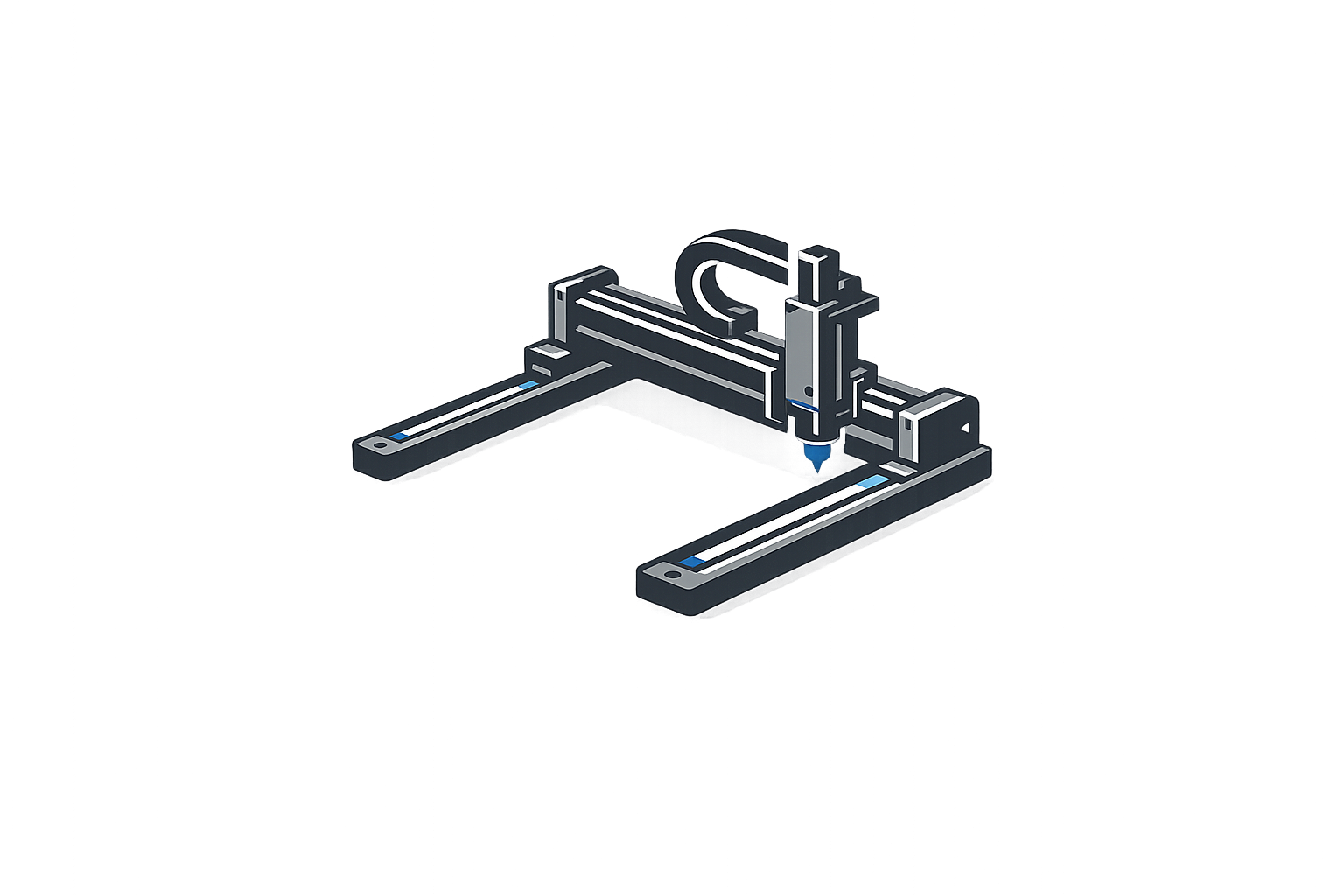
Custom Cartesian Robot Systems for Industrial Automation
Multi-axis positioning systems configured according to your required travel, payload, speed, and repeatability. We design the axis structure around your installation space, motor orientation, and end-effector requirements.
- XY, XYZ, XZ and bridge-style gantry configurations
- Ball screw, synchronous belt, rack-and-pinion, or linear-motor drives
- Customized mounting holes and working envelopes
- Drawing-based engineering and structural assembly review
What Is a Cartesian Robot?
A Cartesian robot is an industrial motion system that moves linearly along two or three perpendicular axes (X, Y, and Z). This structure creates a rectangular working envelope. Because the motion principle is rigidly defined by linear guides and actuators, these customized machine structures are typically used for precise positioning, assembly, dispensing, inspection, transfer, and handling applications.
Learn about our multi-axis positioning systemsCartesian Robot Configuration Options
Select the structural foundation based on your spatial constraints, required axes, and payload dynamics.
XY Cartesian Robot
Purchasing Scenario: Positioning, dispensing, inspection, or handling on a flat working area.
Common Constraint: Limited machine height and the need to access several positions on one plane.
Product Solution: Two perpendicular linear axes with configurable travel, mounting plate, motor direction, and cable routing.
Buyer Benefit: A rectangular working envelope that can be integrated directly into a machine frame without excess vertical clearance.
XYZ Cartesian Robot
Purchasing Scenario: Pick-and-place, assembly, screwdriving, loading, unloading, or inspection at different heights.
Common Constraint: Vertical payload, Z-axis overhang, cycle-time requirements, and restricted installation space.
Product Solution: Three linear axes selected according to stroke, payload, moment load, speed, and end-effector weight.
Buyer Benefit: Controlled movement between multiple heights without requiring a complex six-axis robot for a standard rectangular process path.
XZ or Z-Axis Lifting System
Purchasing Scenario: Vertical insertion, lifting, loading, pressing, dispensing, or component transfer.
Common Constraint: Gravity load, brake requirements, axis rigidity, and safe holding during a power interruption.
Product Solution: Supported vertical structure with an appropriate drive mechanism, guide arrangement, motor brake, and sensor layout.
Buyer Benefit: The vertical motion can be matched precisely to the actual load and machine opening dimensions.
Gantry Cartesian Robot
Purchasing Scenario: Handling large workpieces, transferring components across production equipment, pallet loading, inspection, or packaging.
Common Constraint: Long travel, wide span, frame deflection, synchronized movement, and machine access.
Product Solution: Bridge or overhead gantry structure with parallel supports and a configurable cross axis.
Buyer Benefit: Large rectangular coverage while keeping the work area below the robot accessible for conveyors or operators.
Long-Stroke Transfer System
Purchasing Scenario: Transferring parts between machines or stations over an extended production line.
Common Constraint: Long travel, floor-space limitations, cable management, installation alignment, and service access.
Product Solution: Belt or rack-and-pinion axis designed around the required travel and transfer load.
Buyer Benefit: Parts can move seamlessly between stations without adding multiple short transfer mechanisms, simplifying line control.
Built Around Your Machine Layout, Not Only a Standard Catalog Size
Industrial buyers frequently have fixed machine-frame dimensions, mounting-hole positions, guarding, cable paths, controller standards, and process heights established before selecting the Cartesian robot. We engineer the axis structure to fit your reality.
We configure the system based on concrete project inputs:
- Machine-frame drawing
- X, Y, and Z travel
- Moving payload
- Cycle time
- Motor mounting direction
- Sensor positions
- Cleanroom/dust restrictions
- Available installation envelope
- Mounting-hole pattern
- End-effector weight & offset
- Required repeatability
- Cable outlet direction
- Controller interface
- Maintenance access
A machine drawing, payload estimate, and target cycle time are usually sufficient for an initial configuration review.
Drive-System Selection
The transmission method determines the speed, repeatability, and maximum travel of the axis.
Ball Screw Drive
Selected for high positioning repeatability, rigidity, and vertical-axis applications. Constrained by critical speed limitations over long travels and requires regular lubrication.
Synchronous Belt Drive
Ideal for longer travel, high speed, and lower moving mass. Requires attention to belt tension and offers slightly lower positioning rigidity compared to screws.
Rack-and-Pinion Drive
Suitable for extended travel and heavier structures, particularly in large gantry systems. Requires precise installation alignment for smooth gear engagement.
Linear Motor Drive
Provides direct-drive movement with reduced mechanical transmission, offering high speed and acceleration. Requires linear encoders and careful heat management.
| Drive Method | Suitable Travel | Typical Purchasing Scenario | Main Design Constraint | Reason to Select It |
|---|---|---|---|---|
| Ball Screw | Short to Medium | Precision assembly, dispensing, Z-axis | Screw whipping at high speeds/long strokes | High thrust and excellent repeatability |
| Synchronous Belt | Medium to Long | Packaging, pick-and-place, transfer | Belt stretching, lower rigidity | High speed over longer distances |
| Rack-and-Pinion | Long to Very Long | Heavy gantry machining, palletizing | Backlash management, lubrication | Unlimited travel length capability |
| Linear Motor | Medium to Long | Semiconductor, high-speed inspection | Cost, heat dissipation, magnetic attraction | Zero backlash, ultra-fast settling time |
Main Components of a Cartesian Robot
Understanding the internal architecture helps in specifying the correct payload, rigidity, and maintenance requirements for machine integration.
Structural Base / Frame
Provides the mounting foundation. Aluminum extrusions offer flexibility, while steel bases provide higher rigidity for heavy payloads.
LM Guides
Linear motion guides manage the moment loads and ensure travel straightness under dynamic forces.
Drive Mechanism
The ball screw, belt, or rack that converts motor rotation into linear carriage movement.
Servo Motor & Encoder
Provides controlled torque and position feedback to the controller interface.
Sensors & Stops
Home and limit sensors define the working envelope, backed up by mechanical stops for safety.
Cable Carrier
Manages moving cables and air lines to the end-effector without tangling during rapid cycles.
Application Scenarios
We configure the axis structure to address the specific constraints of your production environment.
Precision Assembly & Screwdriving
Configured to handle tool reaction forces and ensure Z-axis rigidity during the fastening sequence and fixture alignment.
Pick-and-Place & Handling
Optimized for part weight, gripping methods, high acceleration over transfer distances, and strict cycle time limits.
Dispensing & Adhesive Application
Designed for path consistency, stable nozzle height, controlled corner speeds, and varied workpiece sizes.
Inspection & Testing
Engineered to support camera payloads with high positioning repeatability, low vibration, and precise scan paths.
Packaging & Palletizing
Built around package dimensions, production rates, wide gripper layouts, and line height requirements.
Semiconductor & Electronics
Customized for open-frame integration, compact heights, cleanliness standards, and precise equipment access.
Technical Selection Parameters
Preparing these specifications allows our engineering team to recommend the correct axis configuration and provide an accurate quotation.
| Axis Configuration | Configured according to the approved project specification |
|---|---|
| X / Y / Z Travel | Configured according to the approved project specification |
| Effective Working Envelope | Configured according to the approved project specification |
| Horizontal / Vertical Payload | Configured according to the approved project specification |
| End-Effector Weight & Offset | Configured according to the approved project specification |
| Required Repeatability | Configured according to the approved project specification |
| Max Speed & Acceleration | Configured according to the approved project specification |
| Target Cycle Time | Configured according to the approved project specification |
| Drive Method & Guide Type | Configured according to the approved project specification |
| Motor Interface & Controller | Configured according to the approved project specification |
| Mounting & Cable Direction | Configured according to the approved project specification |
| Protection / Cleanliness | Configured according to the approved project specification |
Accuracy, Repeatability and Mechanical Stability
Understanding motion metrics is critical for buying decisions. A camera-inspection application may prioritize repeatability and vibration settling time, while a long-stroke transfer application may prioritize frame alignment, travel straightness, and stable operation over the entire span.
Positioning Accuracy vs. Repeatability
Accuracy is how close the carriage reaches a commanded target. Repeatability is the variance when returning to the same target multiple times.
Straightness and Parallelism
Crucial for multi-axis systems to ensure the X and Y axes remain perfectly perpendicular without binding during travel.
Rigidity and Deflection
Measured under load to ensure the Z-axis or gantry bridge does not sag beyond acceptable tolerances during operation.
Engineering and Approval Process
The production schedule is confirmed after the axis configuration, purchased components, drawing approval, quantity, and inspection scope are fixed.
Application Review
Parameter Confirmation
Structure Selection
Arrangement Drawing
Interface Confirmation
Quotation Approval
Sample/Prototype
Assembly & Inspection
Trial & Documentation
Packing & Shipment
Cartesian Robot vs. SCARA and Six-Axis Robot
Choosing the right robotic structure depends on the working envelope, payload, and required orientation.
| Feature | Cartesian Robot | SCARA Robot | Six-Axis Robot |
|---|---|---|---|
| Working Envelope | Rectangular (Scalable) | Cylindrical / Circular | Spherical / Complex |
| Long-Travel Capability | Excellent (Gantry setups) | Limited by arm reach | Requires linear track |
| Payload Support | High (Rigid support) | Medium (Z-axis limits) | Varies by model |
| Mechanical Complexity | Lower (Independent axes) | Medium | High (Coupled joints) |
| Typical Applications | Dispensing, handling, gantry | Fast planar assembly | Welding, complex manipulation |
When NOT to Choose a Cartesian Robot
- The tool requires frequent changes in orientation (pitch, yaw, roll).
- The motion path must reach around or inside obstacles.
- The process requires complex angular manipulation (e.g., 3D welding).
- A compact circular work envelope is more appropriate for the cell layout than a rectangular one.
What Determines the Cost of a Cartesian Robot System?
A small two-axis positioning unit and a long-stroke, heavy-load XYZ gantry system should not be compared using only the phrase "Cartesian robot price." The quotation separates the axis structure, drive method, motors, and inspection scope so buyers can compare equivalent configurations.
- Number of axes & travel length
- Payload and moment load
- Drive type (Screw vs. Linear Motor)
- Frame size and gantry span
- Motor and controller selection
- Required speed and accuracy
- Cable carriers & guarding
- Inspection documentation & Qty
Engineering and Manufacturing Capability
We build customized motion systems based on verified project inputs, ensuring mechanical integration aligns with your machine design.
- Engineering of customized single-axis and multi-axis structures based on customer machine drawings.
- Integration of LM guides, drive mechanisms, motors, sensors, and mounting platforms.
- Verification of travel, sensor operation, mounting dimensions, and repeated positioning before shipment.
- Sample or trial-unit approval before batch production when required by the project scope.
What to Provide for a Configuration Review
To receive an accurate technical proposal, please prepare the following details:
Related Multi-Axis Positioning Systems
Frequently Asked Questions
What is a Cartesian robot used for?
What are the main components of a Cartesian robot?
What is the difference between a Cartesian robot and a gantry robot?
How do I choose between a Cartesian robot and a SCARA robot?
Which drive system is suitable for a long-stroke Cartesian robot?
What information is needed to quote a custom XYZ robot?
How is Cartesian robot repeatability verified?
Can a Cartesian robot be integrated with an existing PLC or controller?
What determines the cost of a Cartesian robot?
Can a Cartesian robot be customized for packaging or assembly equipment?
Send Your Application Requirements for a Cartesian Robot Review
Our engineering team needs the working envelope, payload, cycle time, repeatability, mounting condition, and quantity before recommending a structure.
Email Us
support@mro-sourcing.com
Call Us
16620975588
Location
Shenzhen, Guangdong Province, China